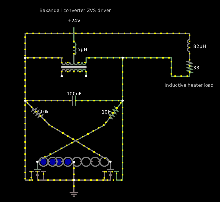
I tried simulating a Baxandall converter ZVS driver circuit with circuit.js; here's the circuit:
$ 1 1e-7 2.9224283781234943 50 100 43
l 256 64 256 112 0 0.0005 0.025188214463181376
169 224 160 224 112 0 0.000009999999999999999 1 8.881784197001252e-16 6.317123571343775 6.342311785806956 0.99
c 128 224 384 224 0 1e-7 -40.777875024550454 0.001
w 128 224 128 112 0
w 128 112 224 112 0
w 288 112 384 112 0
w 384 224 384 432 0
R 256 64 256 16 0 0 40 24 0 0 0.5
f 352 384 352 432 32 1.5 0.02
f 160 384 160 432 40 1.5 0.02
w 176 432 256 432 0
w 256 432 336 432 0
g 256 432 256 464 0 0
w 368 432 384 432 0
w 384 224 384 112 0
w 144 432 128 432 0
w 128 432 128 224 0
x 166 -8 353 -5 4 12 Baxandall\sconverter\sZVS\sdriver
w 256 384 256 432 0
w 160 384 336 288 0
r 336 288 384 224 0 10000
r 128 224 192 288 0 10000
w 192 288 352 384 0
34 fwdrop\q3.2 1 9.32e-11 0.042 5.356678529866179 0 1
162 304 384 272 384 2 fwdrop\q3.2 0 0 1 0.1
34 fwdrop\q3.2-2 1 9.32e-11 0.042 5.356678529866179 0 1
162 208 384 224 384 2 fwdrop\q3.2-2 0 0 1 0.1
162 192 384 208 384 2 fwdrop\q3.2-2 0 0 1 0.1
162 320 384 304 384 2 fwdrop\q3.2-2 0 0 1 0.1
162 352 384 320 384 2 fwdrop\q3.2-2 0 0 1 0.1
162 272 384 256 384 2 fwdrop\q3.2 0 0 1 0.1
162 224 384 256 384 2 fwdrop\q3.2-2 0 0 1 0.1
162 160 384 192 384 2 fwdrop\q3.2-2 0 0 1 0.1
o 2 16 0 5123 320 51.2 0 2 2 3
By itself this produces a somewhat disappointing peak voltage multiplication of about 3×, or 6× peak to peak, with a resonant peak about 158 kHz on the FFT, which is high enough for inductive heating of even non-ferrous metals in some cases. The two strings of four 3.2-volt blue LEDs limit the gate voltages on the two N-channel MOSFETs to about 9.9 volts (2.4 volts per LED, which is a bit unrealistic...) so they don't burn out, while the 10k resistors limit the current through the LEDs to about 5 mA.
The resonant frequency is of course 1/(2π√(LC)), and in this case the relevant L is the 10 μH of the inductor, and the C is the 0.1 μF of the capacitor, 159.1 kHz, which is right. The peak current in the tank circuit is about 7.5 amps, 1500 times the current through the LEDs.
If I load the output (parallel to the capacitor) with a resistive load, then somewhere below about 180 Ω, the output collapses. For it to recover, the load evidently needs to be 330 Ω or more. It’s possible to use an inductive load of 82 μH with 33 Ω equivalent series resistance and have it work:
$ 1 1e-7 2.3728258192205156 50 100 43
l 256 64 256 112 0 0.0000049999999999999996 1.3758031682752978
169 224 160 224 112 0 0.000009999999999999999 1 0 -4.784632558596629 -3.4088293903213227 0.99
c 128 224 384 224 0 1e-7 33.040933721242446 0.001
w 128 224 128 112 0
w 128 112 224 112 0
w 288 112 384 112 0
w 384 224 384 432 0
R 256 64 256 16 0 0 40 24 0 0 0.5
f 352 384 352 432 32 1.5 0.02
f 160 384 160 432 40 1.5 0.02
w 176 432 256 432 0
w 256 432 336 432 0
g 256 432 256 464 0 0
w 368 432 384 432 0
w 384 224 384 112 0
w 144 432 128 432 0
w 128 432 128 224 0
x 166 -8 353 -5 4 12 Baxandall\sconverter\sZVS\sdriver
w 256 384 256 432 0
w 160 384 336 288 0
r 336 288 384 224 0 10000
r 128 224 192 288 0 10000
w 192 288 352 384 0
34 fwdrop\q3.2-2 1 9.32e-11 0.042 5.9498493010683156 0 0.1
162 208 384 224 384 2 fwdrop\q3.2-2 0 0 1 0.01
162 192 384 208 384 2 fwdrop\q3.2-2 0 0 1 0.01
162 320 384 304 384 2 fwdrop\q3.2-2 0 0 1 0.01
162 352 384 320 384 2 fwdrop\q3.2-2 0 0 1 0.01
162 224 384 256 384 2 fwdrop\q3.2-2 0 0 1 0.01
162 160 384 192 384 2 fwdrop\q3.2-2 0 0 1 0.01
162 304 384 272 384 2 fwdrop\q3.2-2 0 0 1 0.01
162 272 384 256 384 2 fwdrop\q3.2-2 0 0 1 0.01
w 128 112 128 48 0
w 128 48 560 48 0
w 384 112 512 112 0
r 560 112 560 160 0 33
w 512 112 512 160 0
w 512 160 560 160 0
l 560 112 560 48 0 0.000082 0.3059284467964981
x 494 188 623 191 4 12 Inductive\sheater\sload
o 2 16 0 5123 80 6.4 0 2 2 3
The original Baxandall converer circuit is by Peter Baxandall from 1959.